
Signal Quality Validation for Reliable Motor Current Signature Analysis
Applying signal validation before fault analysis has huge benefits for the diagnostic outcomes of ALERTech-IM™ in challenging field conditions.
30 May, 2026
Motor Current Signature Analysis (MCSA) is a widely used technique for detecting electrical and mechanical faults in rotating machines. The approach relies on the assumption that the measured stator current is a stable, near-sinusoidal signal that accurately reflects motor operating behavior. When this condition is satisfied, spectral analysis of the current enables the identification of fault-related frequency components with good reliability, particularly under steady-state and well-controlled operating conditions. In industrial environments, this assumption is frequently violated due to a range of signal quality degradations.
Measured current signals may be dominated by broadband electrical noise, exhibit insufficient amplitude under noisy operating conditions, or display half-wave and clipped sinusoidal waveforms due to sensor saturation or improper scaling. Additional challenges include spiked or periodic noise contamination, dome-shaped spectral energy concentrated near the supply frequency, and DC offset introduced by grounding issues or data acquisition artifacts. These distortions can render the current signal unsuitable for direct MCSA processing and often lead to false fault indications, unstable spectral features, and reduced diagnostic reliability.
Based on this field experience, we introduced signal quality validation as an explicit design requirement within ALERTech-IM™, our smart diagnostic solution for induction motor health. Rather than treating signal conditioning as an assumed prerequisite, signal validation is implemented as a mandatory preprocessing step before MCSA is applied.
Signal Quality Validation as a Design Requirement
Each acquired current signal segment is evaluated against a set of deterministic, physically motivated criteria derived from expected motor electrical behavior. Signals that satisfy these criteria are forwarded to downstream fault detection algorithms. Signals that fail validation are rejected and excluded from diagnosis. This approach prevents spurious inputs from corrupting spectral features and fault indicators, without requiring changes to established MCSA fault models.
By making signal validation explicit and automatic, the framework ensures that diagnostic results are based only on physically meaningful data, even under challenging field conditions.
Classification of Signal Disturbances and Validation Criteria
The validation framework targets signal conditions that we have repeatedly encountered during industrial deployments. Each condition is associated with a plausible physical or measurement-related cause and is evaluated using transparent statistical metrics. Representative waveforms and spectra for each case are referenced below and shown in the accompanying figures.
Noise-Dominated Signals
Noise-dominated signals are characterized by random, non-periodic fluctuations with little or no sinusoidal structure, as seen in Figure 1. These signals typically arise from severe electromagnetic interference, loose connections, or sensor malfunction. Temporal correlation between time-shifted samples is evaluated, and signals exhibiting insufficient correlation are classified as noise-dominated and rejected.
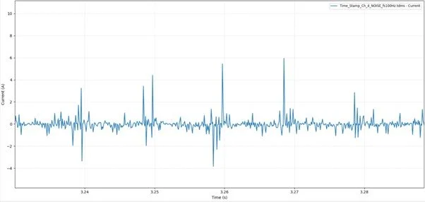
Figure 1: Gaussian noise-dominated current signal
Insufficient Signal Amplitude
In some operating conditions, the current waveform appears sinusoidal but has very low amplitude, as illustrated in Figure 2. This is commonly observed during motor standstill, extremely light loading, or incorrect sensor scaling. The RMS phase current is compared against a minimum percentage of the motor’s rated current. Signals below this threshold are rejected, as they do not reliably carry fault-related modulation information.
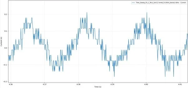
Figure 2: Low-amplitude current signal under light-load conditions
Clipped Sinusoidal Signals
Half-wave or clipped sinusoids, shown in Figure 3, result from sensor saturation, ADC clipping, or faults in the signal conditioning chain. These waveforms exhibit strong asymmetry and introduce artificial harmonics into the spectrum. Waveform symmetry is quantified using statistical skewness, and signals exceeding acceptable skewness limits are rejected.
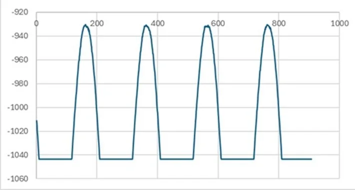
Figure 3: Clipped current waveform due to sensor saturation
Spiked or Periodic Noise Contamination
Spiked or periodically contaminated signals contain sharp transients or repetitive disturbances that spread energy across a wide frequency range, as seen in Figure 4. Such contamination obscures fault-related sidebands and destabilizes spectral metrics. A sinusoidality measure, defined as the ratio of fundamental energy to total spectral energy, is used to evaluate these signals. Signals with insufficient energy concentration at the fundamental frequency are rejected.

Figure 4: Current signal contaminated by spiked or periodic noise
Dome-Shaped Spectrum Near Supply Frequency
In certain cases, the spectrum around the supply frequency appears broadened or dome-shaped rather than sharply defined, as illustrated in Figure 5. This behavior may be caused by electrical instability, excessive noise, or inadequate spectral resolution. Energy in near-sidebands is compared with energy at the center frequency, and signals exhibiting excessive spreading are excluded from analysis.
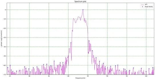
Figure 5: Dome-shaped spectrum around the supply frequency
DC Offset Contamination
DC offset contamination, shown in Figure 6, shifts the waveform away from zero due to sensor bias, grounding issues, or analog front-end faults. This offset distorts low-frequency spectral content and affects modulation-based fault indicators. The magnitude of the DC component is compared to the RMS value of the AC component, and signals exceeding acceptable ratios are rejected.
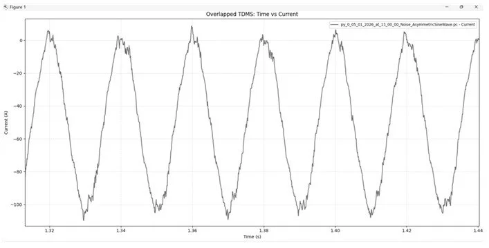
Figure 6: DC Offset Contamination
Complementary Physical Measures to Improve Signal Quality
While software-based validation filters unreliable signals, improving signal quality at the source remains important. The following physical measures have proven effective in practice:
> Rerouting sensor cables away from high-interference paths: Reduces electromagnetic noise pickup and lowers the noise floor.
> Improving grounding and avoiding ground loops: Minimizes DC offset, low-frequency drift, and artificial harmonics.
> Applying proper shielding and signal conditioning: Limits external interference and preserves spectral energy concentration.
Together, these measures strengthen signal integrity at the source and complement software-based validation by reducing the likelihood of spurious signals entering the diagnostic pipeline.
Impact on Diagnostic Reliability
Applying signal quality validation before fault analysis has a direct and measurable impact on the reliability of diagnostic outcomes. The key benefits observed in practice are outlined below.
Reduction of False Alarms
By rejecting distorted or non-physical signals before analysis, the system avoids generating fault indicators from noise, clipping, or measurement artifacts.
Impact: Fewer false positives and reduced unnecessary maintenance actions.
Improved Stability of Spectral Features
Validation ensures that spectral analysis is performed only on signals with consistent sinusoidal structure and sufficient signal quality.
Impact: Fault-related frequency components remain stable over time, improving trend reliability.
Increased Confidence in Diagnostic Conclusions
When diagnostics are based on validated signals, detected anomalies are more likely to reflect actual machine behavior rather than measurement issues.
Impact: Higher trust in diagnostic results by engineers and maintenance teams.
Improved Fault Trend Interpretability
Excluding spurious data points prevents abrupt jumps or discontinuities in fault indicators.
Impact: Clearer fault progression trends and easier correlation with operating conditions.
Robust Operation Across Varying Field Conditions
Signal validation enables consistent diagnostic performance despite variations in load, environment, and installation quality.
Impact: Reliable fault detection in real industrial operating conditions.
Conclusion
Reliable motor fault diagnosis depends on input signal integrity, not only on advanced analytical or spectral algorithms.
Real industrial environments frequently produce distorted or unreliable signals, even when good installation and wiring practices are followed.
Physical corrective measures improve signal quality but cannot fully eliminate transient or operating-condition-related issues.
Systematic signal quality validation before MCSA ensures that fault analysis is performed only on physically meaningful data.
Integrating signal validation into ALERTech-IM bridges the gap between real-world measurements and dependable diagnostic results.
Signal quality validation is a foundational design element, not an optional add-on, in a robust motor condition monitoring system.